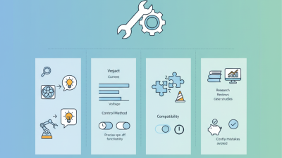
Choosing the right Motor Controller is not a simple matter of matching voltage and current. It is a system decision that affects efficiency, safety, precision, and service life. The controller must work with the motor, load, power supply, feedback devices, and operating environment.
The U.S. Department of Energy reports that motor-driven equipment can represent more than half of industrial electricity consumption. Even a small control mistake can therefore create measurable energy waste. In variable-speed applications, the correct controller can reduce unnecessary acceleration, braking, and heat generation. However, efficiency ratings alone do not tell the whole story. A controller operating inside a dusty cabinet may perform differently from one tested in a clean laboratory.
The International Energy Agency’s Global EV Outlook highlights the rapid growth of electric mobility and power-electronics demand. This trend is increasing expectations for compact thermal design, regenerative braking, and reliable communication. A suitable Motor Controller should support the motor’s rated voltage, peak current, continuous torque, and control method. It should also match the application’s duty cycle, ambient temperature, enclosure rating, and maintenance capability.
Look beyond the product label.
Engineers should verify technical data through manufacturer manuals, independent testing, and field experience. Standards from organizations such as IEC and UL can provide useful safety and performance guidance, but certification does not replace application analysis. A controller may appear oversized and still fail during repeated starts. Another may be affordable but difficult to configure after installation. That is where careful selection matters. This guide examines the practical criteria, common compromises, and often-overlooked questions behind choosing the right Motor Controller.
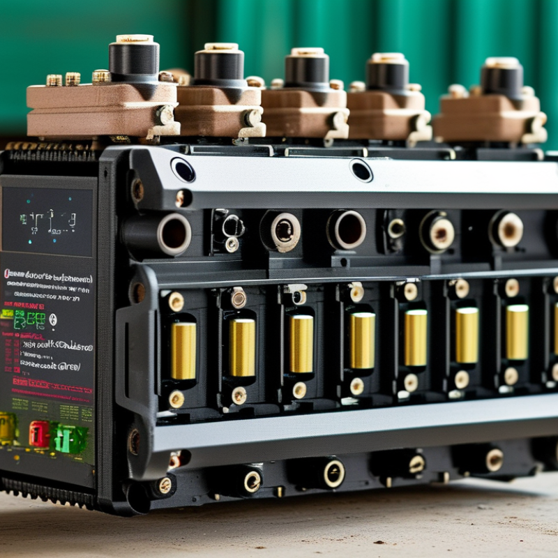
Begin by matching the motor’s rated voltage, current, and power. A 24-volt motor should not be connected to a controller designed only for 12 volts. Check the motor nameplate and measure the supply voltage under load. Voltage affects speed, while current determines torque and heat. Calculate power with voltage multiplied by current, but do not treat that result as the whole story. Startup current can briefly reach several times the running current. The controller must survive that demand.
Speed ratings also matter. Confirm the motor’s maximum revolutions per minute and the controller’s adjustable speed range. A controller operating near its limit may produce unstable movement or excess heat. Duty cycle deserves equal attention. A motor running for two minutes every hour needs less thermal capacity than one operating continuously. Read both continuous and peak current ratings. Peak figures can look impressive, yet they may last only a few seconds.
In workshop testing, I check the controller with the motor attached to its real load, not just an unloaded shaft. That detail is easy to miss. I monitor case temperature, wiring temperature, acceleration, and noise during repeated starts. Leave practical margin, often 20 to 30 percent, for changing loads and imperfect cooling. Still, oversized equipment is not automatically better. It may reduce control sensitivity or increase cost. Review the manufacturer’s technical documentation, then verify the figures in your application. A cool enclosure today may become hot after an hour.

Choosing the right motor controller starts with the motor’s electrical behavior, not its advertised power rating. A brushed DC motor usually needs an H-bridge controller for forward, reverse, braking, and speed control. Check the motor’s stall current carefully. It can be several times higher than its running current.
BLDC motors require electronic commutation through three phases. A six-step controller suits many cost-sensitive systems, while sinusoidal control can reduce vibration and acoustic noise. PMSM motors also use three-phase switching, but field-oriented control is often preferred for smooth torque and accurate positioning. Hall sensors, encoders, or sensorless feedback will affect the controller choice. Do not assume sensorless control works well at zero speed.
AC induction motors need an inverter that manages variable frequency and voltage. Basic V/f control may work for fans and pumps. Vector control is more suitable for changing loads, low-speed torque, or frequent acceleration. In practice, thermal limits matter as much as software features. Measure phase current, DC bus voltage, enclosure temperature, and cooling airflow during real operation.
A selection chart can mislead.
I have seen controllers fail because engineers matched rated watts but ignored starting torque. That mistake is easy to repeat. Leave sensible current headroom, verify regenerative braking behavior, and test the motor under its heaviest expected load. The correct topology should fit the motor, feedback method, duty cycle, and mechanical demands together.
How to Choose the Right Motor Controller?
Size Continuous and Peak Current Using IEC 60034-1 Duty Ratings
Selecting a motor controller starts with the motor’s actual duty, not its catalog horsepower. IEC 60034-1 classifies operating patterns, including S1 continuous duty and intermittent ratings such as S3. For S1, size the controller’s continuous output current above the motor’s rated current at the application voltage. Check ambient temperature, enclosure cooling, and installation altitude too. A warm cabinet can reduce practical current capacity.
Peak current needs a separate calculation. Acceleration, load shocks, plugging, and brief overloads may demand two or three times rated current. Confirm the controller’s peak rating and its allowable duration, not only the headline amperage. For S3 or S6 operation, calculate the effective heating load from current and time. The RMS current over the complete cycle often gives a better thermal reference than the short peak. Include rest periods accurately. They matter.
Measure the machine if possible. Log current during startup, loaded running, braking, and the heaviest repeated cycle. Then compare those readings with the duty rating and controller derating tables. A controller that survives one acceleration may still overheat during repeated cycles. This is where many selections fail. Leave engineering margin, but do not guess blindly; excessive oversizing can weaken low-speed control and raise cost. Recheck the result against the motor nameplate, protection settings, and verified thermal limits. Real machines are less tidy than test sheets.
How to Choose the Right Motor Controller?
Efficiency should be checked at the motor’s real operating point, not only at the advertised peak. Record input voltage, motor current, speed, and load during a typical work cycle. A controller rated at 95% efficiency may perform differently at low speed or during acceleration. Small losses become noticeable inside a sealed cabinet. Heat has nowhere to escape.
Thermal limits deserve practical testing. Check the derating curve for ambient temperature, switching frequency, and continuous current. Mounting orientation also matters. A controller near a hot drive or power supply may reach its limit earlier than expected. Measure the case temperature after several hours of operation. Do not rely on a brief bench test. My first estimate is often too optimistic.
IP ratings must match the installation, not just the product label. An IP65 enclosure can resist dust and water jets, but poor cable glands can weaken the complete assembly. Confirm the rating for the enclosure, connectors, vents, and access panels. Consider condensation, washdown direction, and chemical exposure. Higher protection is not always better. A sealed enclosure may trap heat and reduce efficiency. Leave space for airflow, inspect seals during maintenance, and document temperature readings under real working conditions.
Typical selection reference for evaluating motor controllers by electrical performance, thermal behavior, and enclosure protection. Confirm all values against the controller datasheet and the actual installation conditions.
| Installation Profile | Typical Motor Supply | Recommended Continuous Current Margin | Expected Controller Efficiency | Thermal Limit to Verify | Suggested Cooling Approach | Minimum Practical IP Rating | Key Verification Point |
|---|---|---|---|---|---|---|---|
| Indoor light-duty equipment | 12–48 V DC; low to moderate load | At least 20% above the measured continuous motor current | Approximately 90–97% at rated load | Continuous current at the planned ambient temperature; MOSFET and heatsink temperature | Natural convection with adequate clearance | IP20–IP30 | Check that ventilation openings are not obstructed and that electrical terminals are protected. |
| Enclosed indoor machinery | 24–96 V DC; frequent starts and stops | At least 25–30% above the measured continuous current; verify peak current separately | Approximately 92–98% at rated load | Peak-current duration, switching losses, enclosure temperature, and thermal derating curve | Natural convection or a properly sized heatsink | IP30–IP40 | Confirm that acceleration current does not activate overcurrent protection during the required duty cycle. |
| Factory floor with dust exposure | 24–120 V DC; moderate to high load | At least 30% above the measured continuous current | Approximately 90–97% at rated load | Dust accumulation on cooling surfaces, ambient temperature, and derating above the reference temperature | Sealed heatsink or filtered forced-air cooling | IP54 or higher | IP ratings address enclosure ingress protection; they do not guarantee resistance to corrosive chemicals or impact. |
| Outdoor sheltered installation | 24–120 V DC; variable load | At least 30% above the measured continuous current, including hot-weather conditions | Approximately 90–97% at rated load | Maximum ambient temperature, solar heating, condensation, and low-temperature starting performance | Sealed enclosure with conductive heatsinking; avoid direct solar exposure | IP65 | Verify UV resistance, cable-gland sealing, condensation control, and the controller’s operating-temperature range. |
| Washdown or wet-process area | 24–96 V DC; repeated operation | At least 30% above the measured continuous current; allow for restricted cooling | Approximately 90–96% at rated load | Heat transfer through the sealed enclosure, water temperature, and thermal protection response | Sealed conductive enclosure; do not rely on unprotected fans | IP66–IP69K* | Select the rating according to the actual water pressure, temperature, cleaning chemicals, and washdown procedure. |
| High-inertia or regenerative load | 48–400 V DC; braking or rapid deceleration | At least 30% above continuous current; size peak and regenerative current independently | Approximately 92–98% during motoring; regeneration depends on system design | DC-bus overvoltage, braking-resistor duty, switching temperature, and fault energy | Forced-air or substantial heatsinking, based on calculated losses | IP40–IP65 | Confirm braking control, regenerative-energy handling, capacitor ratings, and overvoltage shutdown thresholds. |
A motor controller should be judged beyond rated voltage and current. The IEA’s Energy Efficiency 2023 report states that industry consumes about 37% of global final energy. Motor systems make up a substantial share of that demand. Small control losses can become expensive over long operating hours.
Start with IEC 61800-5-1 safety requirements. Check insulation coordination, protective bonding, touch protection, and fault behavior. The enclosure should match the installation environment, especially where dust, moisture, or vibration is present. Do not trust a generic “compliant” claim. Request test evidence and the applicable edition of the standard.
EMC performance requires separate attention. IEC 61800-3 addresses electromagnetic emissions and immunity for adjustable speed power drive systems. Review the intended environment, cable length, shielding, filters, and grounding method. The wrong installation can defeat a compliant controller. It happens.
Feedback options also shape machine performance. Encoder, resolver, or sensorless control affects speed accuracy, torque response, and low-speed stability. The U.S. Department of Energy’s Motor Systems Market Assessment identifies motor-driven equipment as responsible for roughly 68% of industrial electricity use in the United States. Efficient control matters.
Look for programmable acceleration, torque limits, regenerative handling, safe torque off, diagnostics, and communication protocols. A controller with many features may still be difficult to commission. I have seen troubleshooting become harder when parameters lacked clear names. Test the complete motor-controller-cable combination, not only the controller on a bench.